you are here [x]: Scarlet Star Studios > the Scarlet Letters > steel armature home stretch
<< before
running as fast as i can
after >>
new armature: the man of steel
September 4, 2006
steel armature home stretch
by sven at 9:16 pm
Since I got back from Canada, I've put in 51 hours on the steel armature. It's all done, except for the feet -- which I'm estimating will take another 6 hours.
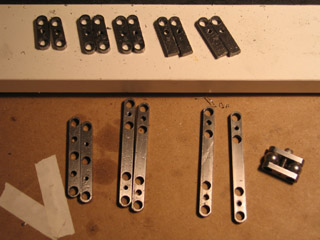
The biggest accomplishment on this project has been getting the sandwich plates radiused (rounded off). Each radius required 18 passes with the milling cutter, shaving off .005" at a time.
In the course of making all those tiny cuts, I managed to reinvent steel wool. As the milling cutter spins, it accumulates a blob of spinning, magnetic, metal-splinter-and-oil paste. This paste -- along with chips and spirals from other cutting operations -- gets all over the worktable. ...Every night I come home with irritating microscopic metal slivers in my fingers, wrists, and elbows. I've started wearing my nitrile gloves while machining. That helps protect my fingers -- but what I really need is to find a sturdy long-sleeved shirt that I'm willing to sacrifice to the metalworking gods.
Even more alarming: A friend in the medical system has forewarned me that I'll now be disqualified from ever getting an MRI scan. Apparently, once upon a time, a fellow came in for a scan who didn't know that he had a tiny metal splinter in his eye. The powerful magnets of the MRI pulled the chip through an artery, and caused a stroke. Thusly, so I'm told, MRI technicians are now supposed to ask if you've ever worked in a machine shop before they let you get scanned.
Yeeeeeeesh...
JIG DESIGN #4
In the course of radiusing the sandwich plates, I discovered that jig design #3 was flawed. I had to spend a day modifying the jig, but it seems to work without fail now.
The trouble was that I was clamping the jig to the rotary table using a lathe chuck. That works very well for a while... But while the chuck is sturdy enough to hold something that's rotating on a lathe, it's not designed to withstand the stresses created by a milling cutter. Eventually its grip loosens.
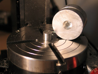
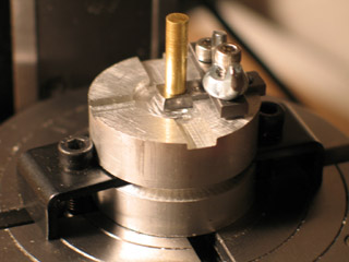
My solution (jig design #4), was to create a centering pin that could plug into the hole in the center of the lathe chuck on one side, and connect into a hole in the bottom of the jig on the other. To make the centering pin, I lathed a round piece of aluminum down to 7/16". I made the hole in the bottom of the jig by using the lathe and a boring tool. These tasks represent my first real work on the lathe, other than drilling balls.
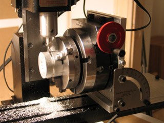
The centering pin does a very good job of locating the jig where I want it on the rotary table. But I still needed a means to firmly hold it down. So, what I did was create a groove in the side of the jig, so I could use regular hold-downs.
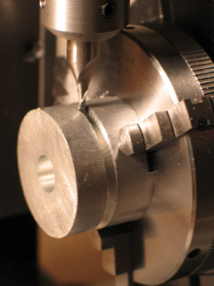
This is a particularly interesting set-up, seen in the two photos above. On the mill's XY table, I've attached a tilting angle table, and set it to 90 degrees. Screwed into the tilting angle table is the rotary table, and screwed into that is the lathe chuck. This arrangement allows me to cut a groove all around the jig.
DRILLING BALLS
Making the sandwich plates is the most time-consuming and challenging part of making the armature. This go-around, I decided to get that ordeal out of the way first, and then move on to easier things: drilling balls, and brazing them onto rods.
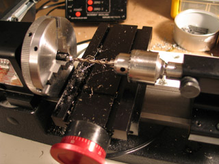
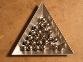
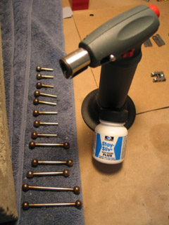
I've been trying to fine-tune my process for drilling balls. The balls pictured are all 5/16" diameter type 302 stainless steel balls purchased from smallparts.com. [They're almost exactly the same size as the 8mm beads that I've used on previous armatures.]
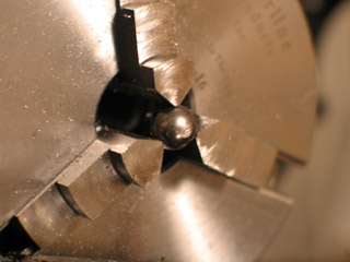
Step 1: Put a ball in the lathe chuck and file a small flat area (~1/16" wide) using a bastard file. Tom Brierton recommends doing this with the lathe turned on. I found that for me it works better to just spin the wheel by hand while the lathe is turned off, filing with not much pressure.
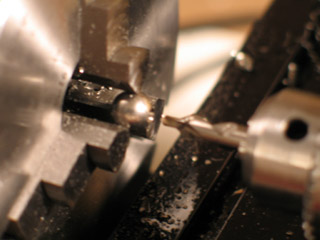
Step 2: Put a #2 center drill in a small drill chuck in the tail stock. Bring it to the point where it's touching the ball. Put a drop or two of oil on the center drill. Turn the lathe on, and bring the motor up to 1800 RPM. [I haven't been able to determine what the technically correct turning speed should be, but this seems to work based on trial and error.] Feed the drill into the ball fairly quickly, three and a half turns (.175"). This creates a small hole with just a little bit of lip. Don't use the handle on the hand wheel -- keep your hand on the edges of the wheel, or you won't be able to control its speed of entry adequately.
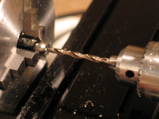
Step 3: Remove the drill chuck, take out the center drill, replace it with a 1/8" drill, and reassemble. I want to make a hole that goes halfway through the ball. If the ball is 5/16" (.3125"), halfway through is .15625"... But for my purposes, .15" is close enough. Each turn of the handwheel is .05", so it'll take three turns of the handwheel to get the drill in. Oil the drill and back it up one turn. Turn the lathe on, and move the drill forward four turns. Use a fiarly fast feed.
Step 4: Repeat, repeat, repeat. Don't forget to drill extra balls, to accommodate for mistakes later on in the process.
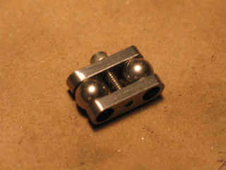
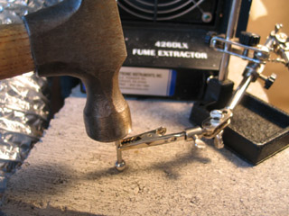
BRAZING BALLS ONTO RODS
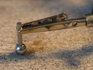
LIO recommends brazing with the ball on top of the rod. Tom Brierton recommends brazing with the rod on top of the ball, held in a "helping hands" tool. In Laika's "The Making of Believe" video, I can see that they use LIO's method. [Not surprising, given that LIO used to work there.] ...However, because I'm familiar with the helping hands tool, I opt for Tom's method.
When I braze, I'm using .030" diameter J.W. Harris brand Safety-Silv 56 cadmium-free silver solder (that's 56% silver), and J.W. Harris brand Stay-Silv white brazing flux. I find that two small clippings of soldering wire is adequate, each between 1/32" and 1/16" in length.
For a heat source, I'm using a butane microtorch that came with a creme brulee set. [You can also buy microtorches at a hardware store.] If I recall correctly, Safety-Silv 56 melts at about 900 degrees. According to the Welder's Handbook, propane burns at 3800 degrees Fahrenheit, and butane burns at 3900 degrees -- so butane should work just as well as the standard propane torch.
I find it takes about 15 seconds of heat to get the Safety-Silv to melt. LIO says that you should be able to feel the ball sink onto the rod... I experienced that only once; I think it has to do with the shape of the solder snippings you use. [Tom uses shavings off of a larger diameter wire, which is likely to be another experience still.]
Unfortunately, the Safety-Silv melting seems to coincide with the ball discoloring. It turns a sort of iridescent black, like an (artificial) black pearl. Then, as it cools, it turns a brassier color. I'm unhappy about the discoloration... I think I need to look into purchasing "granular oxide remover" or pickling solution to clean the balls. I tried using a steel brush, as LIO suggests, but it seemed to scratch the balls, which is unacceptable.
The worst of the discoloration results from the flux boiling over the sides of the hole. To avoid this, a trick I came up with was to apply flux into the hole using a toothpick. I attempted to use as little flux as possible, while still coating all of the insides of the hole. When I was careful, it seemed that I was able to avoid flux boiling over almost entirely.
BRAZING THE TORSO AND PELVIS
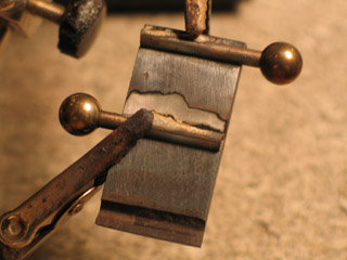
On my previous armature, I was using a solder that was 98% tin, 2% silver -- as opposed to the current stuff, which is 56% silver (and six times more expensive). This solder is much more difficult to use on the torso and pelvis blocks.
I lay down a half-inch long piece of soldering wire on some flux, just to the side of one of the rods that I'm trying to attach. Because the plate is so big, there's a lot of dissipation of heat, making it very difficult to get the wire up to 900 degrees. In the process of getting the metal that hot, the body blocks turn black -- and even rust! -- which I then have to sand off using fine-grit sand paper.
[P.S. I made the grooves for the rods this time using a 1/8" ball-ended milling cutter. I just got it in the mail on Friday. It's going to be necessary pretty soon now, when I get around to making my first step-block joints...]
Looking at LIO's Armature Anatomy 101, I begin to understand why he has the shoulder rods attach into holes, rather than lie lengthwise: a smaller point of contact means less heat dissipation to fight.
I also think I begin to understand why he avoids using "helping hands." The helping hands alligator clips have little springs inside of them that make them close. What happens when you super-heat a spring? It dies! At least one of my clips won't close anymore... It's probably done for. These things are really made for soldering circuitry boards and fusing wires -- they're not meant for such extreme heat.
...
OK, there's plenty more to say -- but I'll leave off there for now.
posted by sven | September 4, 2006 9:16 PM | categories: stopmo