you are here [x]: Scarlet Star Studios > the Scarlet Letters > evolution of the ball-drilling jig
<< before
hand paddles
after >>
cutting rods to size
June 29, 2011
evolution of the ball-drilling jig
by sven at 7:00 am
Drilling balls is a fundamental of armature building. It's a tougher problem than you'd think. At this point, I believe I've gone through seven methods of drilling balls — and I'm still not entirely satisfied.
Today I'd like to do a retrospective of the methods I've tried and discuss their various shortcomings.
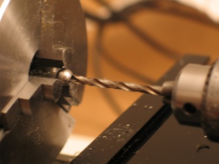
Fig.1: The classic method for drilling holes in balls is to put the ball in a lathe chuck. This is what I did for the Man of Steel back in 2006.
The advantage is that your hole should be perfectly centered. The big problem is that the drill bit wants to push the ball back into the chuck, ruining your control of hole depth. You can try to crank down on the chuck and make it really tight — but the stainless steel ball is harder than the jaws of the chuck and will leave a ball-shaped deformation. Oops.
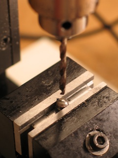
Fig.2: If you put the ball into a milling vise, supported by a riser, you can be sure that your depth will be accurate. However, now you're going to have to worry about getting the hole perfectly centered.
My milling vise has a nice built-in groove for holding the ball in place. But if you use it, where do you measure from to find the center of the ball? You can't use the fixed jaw because you don't know how deep the ball sits in the groove*. You can't use the moving jaw because milling vises pull that jaw down at an angle. If the jaw isn't vertical, there's no way to tell exactly where the ball is making contact.
(*Technically, you could figure it out with geometry — if there was a way to get really precise measurement of the groove's dimensions.)
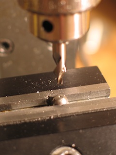
Fig.3: I tried moving the ball over in the vise, so I could use the fixed jaw as a vertical surface to measure from. But with only two points of contact, the ball wants to spin on the Y-axis when the drill makes contact.
To give the vise a better grip, I tried making a grooved insert that attaches to the moving jaw. As I recall, it did an OK job of holding the ball in place… But then I discovered that the ball was deforming the vise jaws. Again, the stainless steel ball is harder than the things holding it. No good.
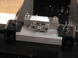
Fig.4: Thinking about sandwich plate joints, I created this jig that would hold two balls from the sides. Several problems… It's fussy to get balls in and out. You have to take the versatile milling vise off the XY table and put a bunch of effort into getting the jig parallel with the milling column. There's a lot of room for compounding errors if the jig itself wasn't milled perfectly straight. It's an overly complicated and irritating solution.
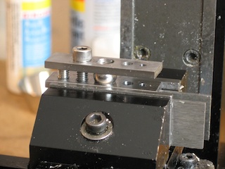
Fig.5: This jig was inspired by step-block joints, and worked pretty well most of the time. It involved a few superfluous steps, though. After clamping a ball in place, I'd fill the hole above it with oil. (The hole held the oil in place quite nicely.) I'd use a cylindrical diamond burr to grind a flat spot on top of the ball. I'd use a center drill to start a hole. Then I'd use a drill to make the actual hole. I've since found a method that doesn't require flattening the ball or using a center drill.
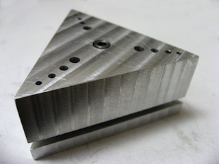
Fig.6: My most recent attempts take their inspiration from this jig by Jeremy Spake. The top holes guide the drill directly to the balls' centers, making center drilling unnecessary. This design is intended for use with a drill press. Unfortunately, I don't have a drill press with depth control that I really trust, so I've had to adapt it for the mill.
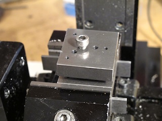
Fig.7: Using three balls guarantees that the top plate will be parallel with the bottom. The hole you make in the ball will be centered, the drill bit won't go into the ball at a funny angle, and you've got good depth control. Excellent!
My version for the milling machine theoretically gives me depth control down to .0005" accuracy. You do have to pull the drill out promptly, though, or else Z-axis backlash might allow the drill to keep going down after you've stopped turning the handwheel.
With Jeremy's design you can do a couple of balls per minute. With mine, you have to re-load the jig every time you want to drill a new ball. Slower… But I'm willing to give up some time for the sake of getting accuracy.
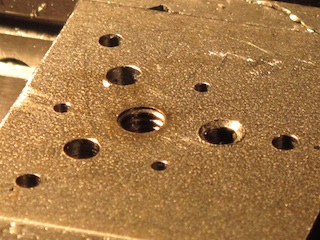
Fig.8: Much to my frustration, I've run into problems with this jig design becoming deformed. If your speed and feed for the drill aren't right, the ball will work harden and the bit can't cut into it anymore. After that point, the drill is simply smashing the ball downward into its seat.
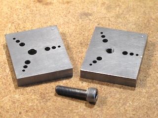
Fig.9: The previous jig was made out of 1018 steel — just about the softest steel you can buy. For my most recent jig I switched to type O1 tool steel, which is harder than 302 stainless. It too has deformed with use, but it survived a much longer time. Progress.
I think the next improvement would be to mill ball cups into the jig… And to really control speed and feed. Unfortunately, I think the only way to achieve that is to purchase a CNC machine. A computer would stepper motors to precisely control the descent of the drill bit.
In the meantime, let's take a closer look at using the current jig design.
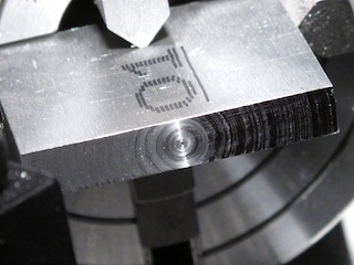
Fig.10: A blog post for another day would discuss the ordeals I've gone through trying to learn how to make the ends of rectangular stock truly flat. Recently I discovered a very simple solution to my woes: four-jawed lathe chucks.
I've been prejudiced against the lathe ever since I couldn't get it to drill balls correctly. Now I discover it's the solution to a problem that's given me countless headaches. Ironic? Anyway, this jig is my first time using the independent-jaws version of the four-jawed chuck.
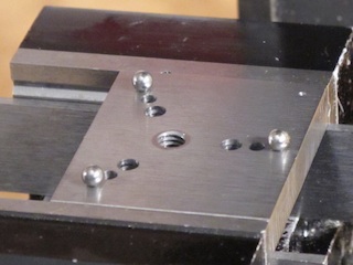
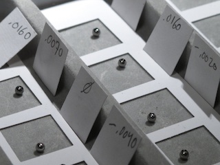
Fig.11: When you put the smallest balls into this jig, they can fall through the larger holes if you accidentally knock them. It's a good idea to put tape or stickers over the larger holes while you work.
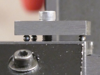
Fig.12: You can see here how parallel the jig's top and bottom plates are. When one of the holes starts deforming, the plates become less parallel. To my surprise, the drilled balls coming out of the damaged jig are useable until the parallelism is strongly compromised.
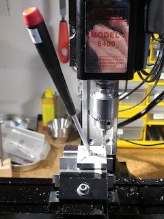
Fig.13: It's very useful to use a ball-nosed hex screwdriver when initially tightening the jig. It allows you to get in at an angle.
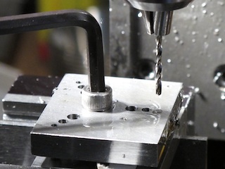
Fig.14: The screwdriver doesn't have enough torque to get the jig really tight. For the final quarter turn, you need to use a regular hex key.
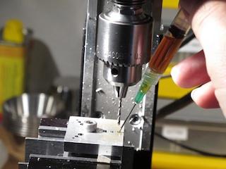
Fig.15: One of my best discoveries for milling has been that you can use a syringe to apply cutting fluid where you need it very precisely. Trying to put oil where you want it with the short spigot of the tin can is messy if not impossible here.
Fig.16: Especially with 1/8" balls, it's difficult to use your big meaty fingers. Tweezers are necessary. Metal tweezers tend to become slightly magnetic, which causes lots of trouble. Using a pair of plastic tweezers works better. Normally I use these for cleaning parts in acid baths… Yet another small detail that saves grief.